Saturday, June 15, 2013

The circuit illustrated below can RE use your thrown tube light

This circuit illustrated below can RE use your thrown tube light. Which usually blinks in normal circuit. A high Dc voltage has advantage to glow a weak florescent tube gets black at one edge. At black end positive voltage should be applied and can be marked as anode and other clear end cathode  can be marked for negative voltage or electron will be supplied.


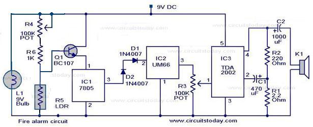
Please see circuit diagram. For converting AC to DC we have used a Rectifier Circuit. Chock/Ballest should be used in series with rectified voltage (DC) is applied to both end of the tube.
Parts LIst:
Choke or you can use 100w bulb
Diode -IN4007 4pcs
Tube Light

Friday, June 14, 2013

Vary simple circuit electronics buzzer

This is vary simple circuit just a couple of resistors. a capacitor and the easily available 555 timer IC.
The 555 is setup as an astable multivibrator operating at a frequency of about 1kHz that products a shrill noise when switched on. The frequency can be changed by varying the 10k resistor.

Parts list:
1. R=10k,  56k,
2. C=1micro farad/15v,  .01 micro farad----(2)
3. IC555
4. Speaker 8ohm,0.5w

Thursday, June 6, 2013

Construction of Fire Alarm Circuit

 Here is a simple alarm circuit based on a Light Dependent Resistor (LDR) and lamp pair for sensing the fire . The alarm works by sensing the smoke produced during fire. The circuit produces an audiobel alarm when the first breaks out with smoke.

When there is no smoke the light from the bulb will be directly falling on the LDR. The LDR resistance will be low and so the voltage across it (below 0.6v). The transistor will be off and nothing happens. When there is sufficient smoke to mask the light from falling on LDR,  the LDR resistance increases and so do the voltage across it. Now the transistor will switch to ON. This gives power to the IC1 and it outputs 5v. This powers the tone generator IC UM66(IC2) to play a music. This music will be amplified by IC3 (TDA 2002) to drive the speaker.Resistor R6 is meant for protecting the transistor when  R4 is turned towards low resistance values. Resistor R2 and R1 forms a feedback network for the TDA2002 and C1 couples the feedback signal from the junction of R1 & R2 to the inverting input of the same IC.

The diode D1 and D2 combination drops 1.4v to give the rated voltage 3.5v to UM66. UM66 cannot withstand more than 4v.


Alarm Circuit Diagram:

Seven Segment Counter Display Circuit Description

Here is the circuit  diagram of a seven segment counter based on the counter IC CD4033. This circuit can be used in conjunction with various circuit where a counter to display the progress adds some more attraction.

IC   NE  555  is wired as an astable multivibrator for triggering the CD 4033. For each pulse the output of the CD 4033 advances by one count. The output of CD 4033 is displayed by the seven segment LED display LT543. Switch S1 is  used to initate the counting. Diode D1 preventgs the risk vof accidental polarity reversal.


Seven Segment Circuit Diagram with Parts List:


R1=47k
R2=220k
R3=47k
R4=470 ohm

C1=.01 micro farad

D1=IN4007

IC=NE 555
IC=CD  4033

LT543 7segment display.


Circuit Diagram of 7 segment  Counter: