Seven Segment Counter Display Circuit Description
Here is the circuit diagram of a seven segment counter based on the counter IC CD4033. This circuit can be used in conjunction with various circuit where a counter to display the progress adds some more attraction.
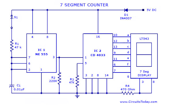
IC NE 555 is wired as an astable multivibrator for triggering the CD 4033. For each pulse the output of the CD 4033 advances by one count. The output of CD 4033 is displayed by the seven segment LED display LT543. Switch S1 is used to initate the counting. Diode D1 preventgs the risk vof accidental polarity reversal.
Seven Segment Circuit Diagram with Parts List:
R1=47k
R2=220k
R3=47k
R4=470 ohm
C1=.01 micro farad
D1=IN4007
IC=NE 555
IC=CD 4033
LT543 7segment display.
Circuit Diagram of 7 segment Counter:

Here is the circuit diagram of a seven segment counter based on the counter IC CD4033. This circuit can be used in conjunction with various circuit where a counter to display the progress adds some more attraction.
IC NE 555 is wired as an astable multivibrator for triggering the CD 4033. For each pulse the output of the CD 4033 advances by one count. The output of CD 4033 is displayed by the seven segment LED display LT543. Switch S1 is used to initate the counting. Diode D1 preventgs the risk vof accidental polarity reversal.
Seven Segment Circuit Diagram with Parts List:
R2=220k
R3=47k
R4=470 ohm
C1=.01 micro farad
D1=IN4007
IC=NE 555
IC=CD 4033
LT543 7segment display.
Circuit Diagram of 7 segment Counter:

No comments:
Post a Comment