Construction of Fire Alarm Circuit
Here is a simple alarm circuit based on a Light Dependent Resistor (LDR) and lamp pair for sensing the fire . The alarm works by sensing the smoke produced during fire. The circuit produces an audiobel alarm when the first breaks out with smoke.
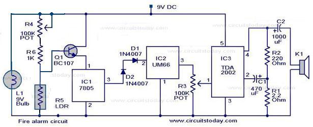
When there is no smoke the light from the bulb will be directly falling on the LDR. The LDR resistance will be low and so the voltage across it (below 0.6v). The transistor will be off and nothing happens. When there is sufficient smoke to mask the light from falling on LDR, the LDR resistance increases and so do the voltage across it. Now the transistor will switch to ON. This gives power to the IC1 and it outputs 5v. This powers the tone generator IC UM66(IC2) to play a music. This music will be amplified by IC3 (TDA 2002) to drive the speaker.Resistor R6 is meant for protecting the transistor when R4 is turned towards low resistance values. Resistor R2 and R1 forms a feedback network for the TDA2002 and C1 couples the feedback signal from the junction of R1 & R2 to the inverting input of the same IC.
The diode D1 and D2 combination drops 1.4v to give the rated voltage 3.5v to UM66. UM66 cannot withstand more than 4v.
Alarm Circuit Diagram:

Here is a simple alarm circuit based on a Light Dependent Resistor (LDR) and lamp pair for sensing the fire . The alarm works by sensing the smoke produced during fire. The circuit produces an audiobel alarm when the first breaks out with smoke.
When there is no smoke the light from the bulb will be directly falling on the LDR. The LDR resistance will be low and so the voltage across it (below 0.6v). The transistor will be off and nothing happens. When there is sufficient smoke to mask the light from falling on LDR, the LDR resistance increases and so do the voltage across it. Now the transistor will switch to ON. This gives power to the IC1 and it outputs 5v. This powers the tone generator IC UM66(IC2) to play a music. This music will be amplified by IC3 (TDA 2002) to drive the speaker.Resistor R6 is meant for protecting the transistor when R4 is turned towards low resistance values. Resistor R2 and R1 forms a feedback network for the TDA2002 and C1 couples the feedback signal from the junction of R1 & R2 to the inverting input of the same IC.
The diode D1 and D2 combination drops 1.4v to give the rated voltage 3.5v to UM66. UM66 cannot withstand more than 4v.
Alarm Circuit Diagram:

No comments:
Post a Comment